
The idea to build a tube amp arose at a party, where all good ideas start. It stayed just an idea for about two years, due to other important things. This winter (2008/2009) the amp got my attention again. So I bought some books, googled for examples, searched explanations and gathered other info. Arnova and I then developed the first drafts for the amp. Later we visited some electronics fairs to get tubes and sockets. I have to be honest, eventually I bought new transformers and tubes. At the fairs I couldn’t find any proper power or output transformers, suitable chokes and half of my EL84 were bad. Reconsider buying old(er) parts.
In an early state I already knew I wanted to build a no-nonsense push-pull amp with EL84 power tubes on each channel. These tubes are very common, quite cheap and there are lots of designs for the taking. I want four EL84 on each channel, because of output power and transformer choice. The output transformers are Amplimo’s 3A524-UL. These transformers can also be used with EL34 tubes (maybe a future project) and have an ultralinear tap at 40%
The power tubes are driven by a ECC81 preamplifier tube. This is a double triode used for amplification and phase conversion. We need a phase convertor for the push-pull power stage.
As this is my timejump to the past, I tried to avoid any semiconductor. No diodebridges and transistorized current sources, unless… Unless you use a power transformer without centertap at it’s secundairy winding, like the Amplimo 6N606. So I can’t use a nice tube to rectify the AC from the power transformers, so I have to use a bridge rectifier to do the job.
The power supply
The power supply is quite simple. From left to right you see the mains-entry, a power switch, a fuse, the transformer, a bridge rectifier (the only semiconductor), a choke and the capacitors.
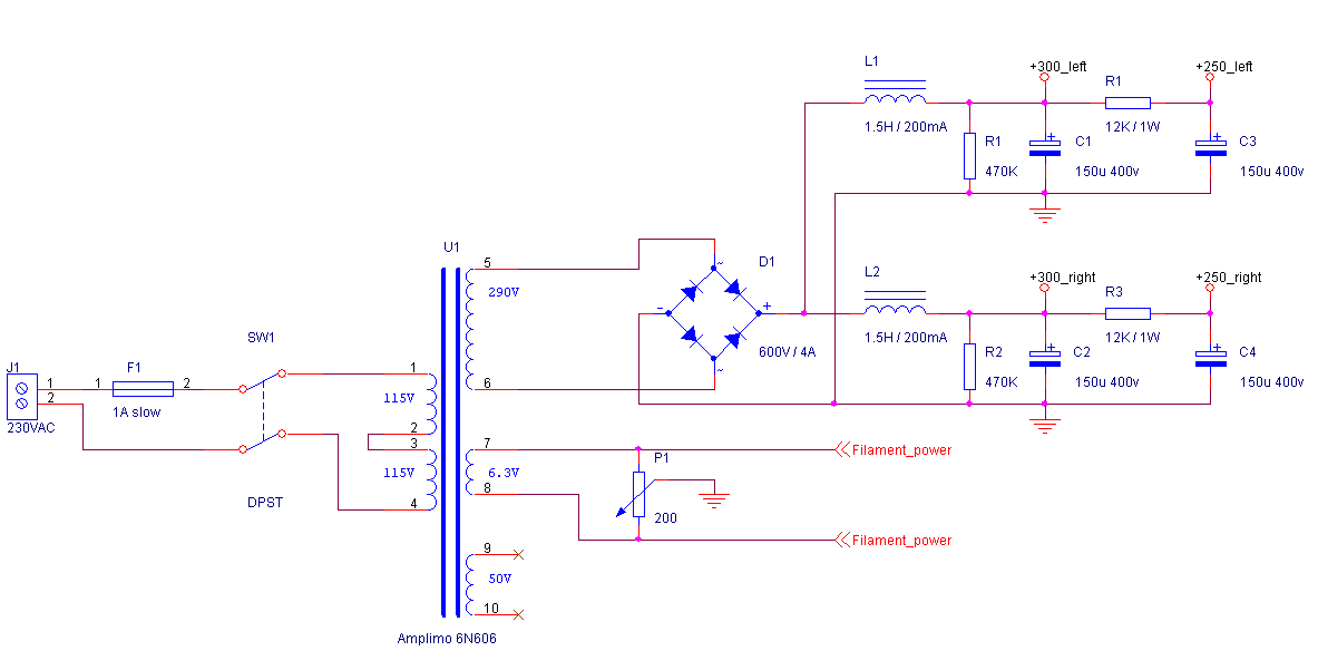
The transformer has three secundairy windings. One produces the high-voltage (HV) of 290VAC. The winding for filament power produces 6.3 volts and the maximum current is 6.8 amps. It also has an additional 50 volts winding you can use to bias power tubes. I don’t use this as I’m using cathode resistors to bias the EL84-tubes.

Warning: The tube amplifier described on this page works with very high voltages that can be lethal. Building tube amplifiers is not for the unskilled electronics hobbyist. Always be carefull !!!
Bill of materials
The only really expensive part is the power transformer, which costs about 80 euros (or 115 USD). Remember you can recycle this power transformer for a four tube EL34 amp. If you’re an electronics enthousiast you’ll probably have the rest of the components in your private stock.
| SW1 | DPST (double pole swingle throw) switch: 250VAC / 1A minimum |
| F1 | Fuse: 250VAC / 1A / slow |
| U1 | Power transformer: Amplimo 6N606 |
| D1 | Bridge rectifier: 600V, 4A (like the Fairchild GBU4J) |
| L1, L2 | Choke: Hammond 156R (200mA, 400V, 56 Ohm DC resistance) |
| R1, R2 | Resistor: 470 KOhm, 1 Watt |
| R3, R3 | Resistor: 16 KOhm, 1 Watt |
| C1, C2, C3, C4 | Electrolytic capacitor: 150uF / 450V |
The amplifier itself
The amplifier is as simple as a push-pull amplifier can be. Your audiosignal comes in left where the volume is set by the potmeter. From there it enters the phase convertor via a capacitor. This capacitor prevents any high DC voltage involved with tubes to go back to the input connector.
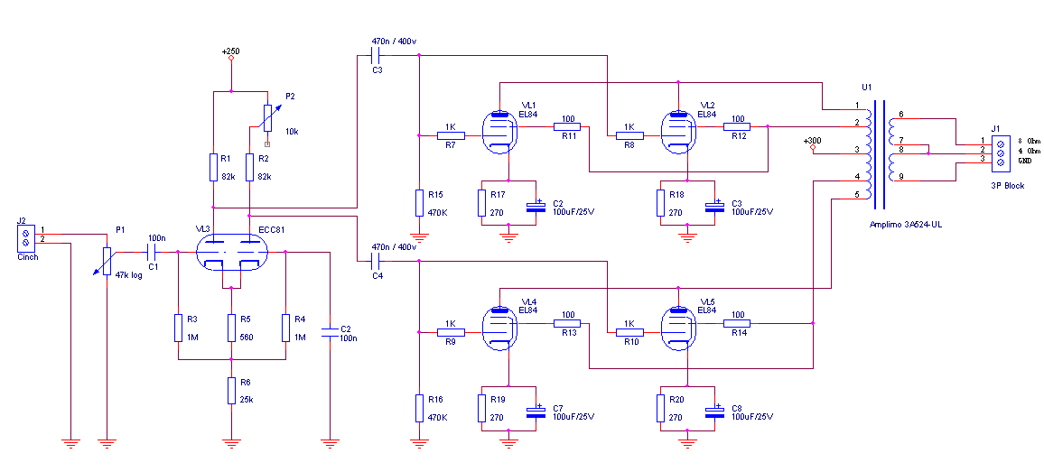
The phase convertor, based on a ECC81 (VL3) double triode, does two things. It amplifies the input signal about 20 times and it also produces an inverted signal. The original signal drives the upper two tubes (VL1 and VL2) while the inverted signal drives the lower tubes (VL4 and VL5).
The amplified and phase inverted signal is coupled to the power tubes by C3 and C4. These capacitors block the high voltage DC-component of the ECC81 anodes so only the audio signal is passed through.
The output stage is the ‘push-pull’ type. This means that the output tubes are driven with opposite signals.
Bill of materials
Keep in mind that the output transformers (about 70 euros each) and power tubes (about 45 euros for a matched quad) are the most expensive parts. Again: remember you can recycle the output transformers for an EL34 push pull amp.
| P1 | Potmeter: 47 KOhm, stereo, logarithmic |
| P2 | Trimpot: 10 KOhm, linear |
| R1, R2 | Resistor: 82 KOhm, 1 Watt |
| R3, R4 | Resistor: 1 MOhm, 1 Watt |
| R5 | Resistor: 560 Ohm, 1 Watt |
| R6 | Resistor: 25 KOhm, 1 Watt |
| R7, R8, R8, R10 | Resistor: 1 KOhm, 1 Watt |
| R11, R12, R13, R14 | Resistor: 100 Ohm, 1 Watt |
| R15, R16 | Resistor: 470 KOhm, 1 Watt |
| R17, R18, R19, R20 | Resistor: 270 Ohm, 1 Watt |
| C1, C2 | Ceramic capacitor: 100 nF, 50V |
| C3, C4 | Polyester film capacitor: 470nF, 630V |
| C5, C5, C7, C8 | Electrolytic capacitor: 100uF / 25V |
| VL1, VL2 | Vacuum tube: EL84 (like the JJ EL84) |
| VL3 | Vacuum tube: ECC81 (like the JJ ECC81) |
| VL4, VL5 | Vacuum tube: EL84 (like the JJ EL84) |
| U1 | Output transformer: Amplimo 3A524-UL |
A few parts are not drawn in the schematic: the tube sockets. Get yourself some magnoval sockets for chassis mounting.
How does it sound?
After all this work I was very very very exciting about the sound of this amp. To be frank, it’s sounds very nice. I haven’t used any equalizer or whatever, just the plain tubes.
That’s it for now. I have to listen to it for a while and then I’ll write more about it.
Pictures
Ready for some images? You can click on at the pictures to see them full size!
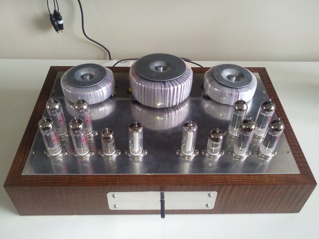
The complete amplifier (volume knob is still missing)
All the connectors at the back (cinch for inputs, 4mm, screwterminals for outputs)

Left channel with the big power transformer and an output transformer
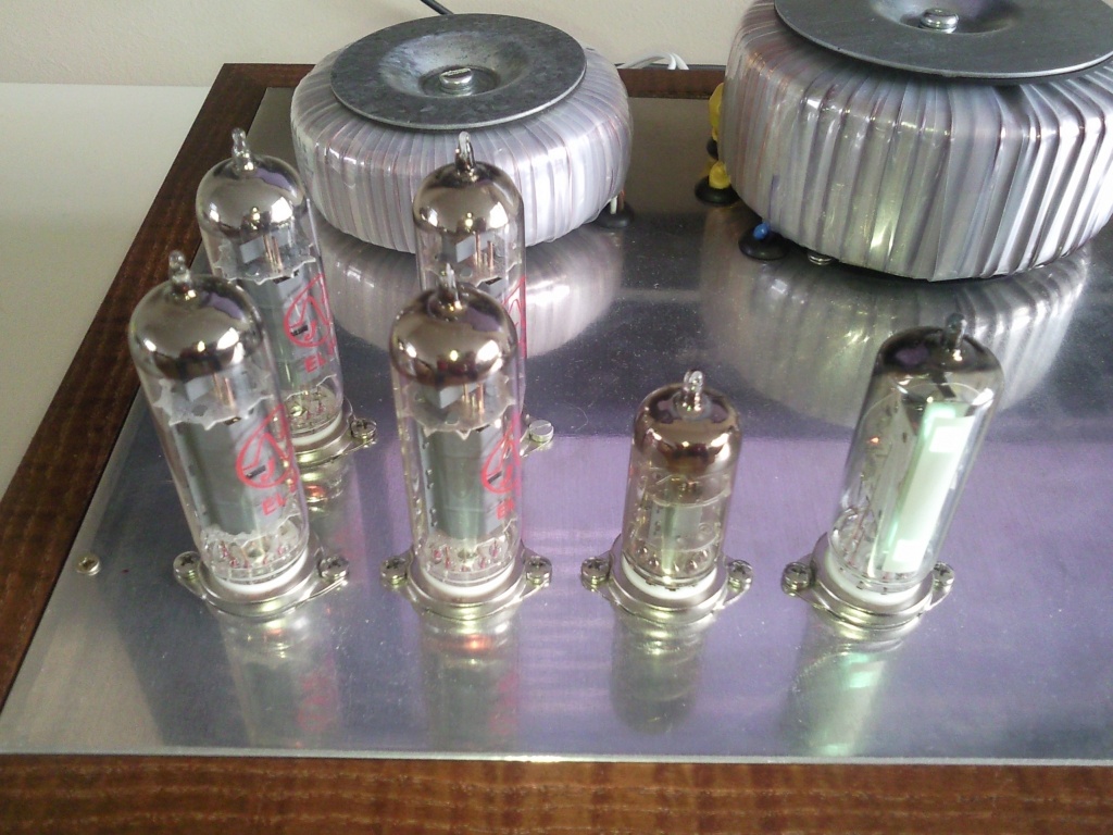
The right channel, check out the nice JJ tubes

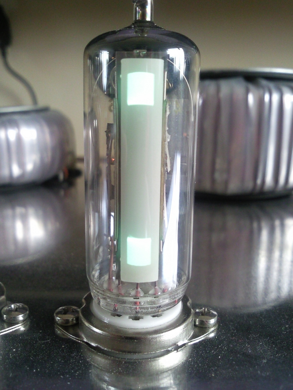
The two level indicators (EM84 tubes)

Level indicator close-up
Volume knob mounted

Input level meters
Neat side project. Input level meters with EM84 indicator tubes. Check the EM84 level meter.
Books and other information sources
– Theorie en praktijk van Buizenversterkers, Peter Dieleman, First edition, 2004, published by ‘Elektor’, ISBN 90-5381-151-6
– Electronic tube handbook, 16th revised edition, 1973, published by ‘De Muiderkring’, ISBN 90-6082-029-0
– Radiotron Designer’s Handbook, 4th edition, 1953, published by Wireless Press,
– I got the Orcad libraries from Eugene Karpov: www.next-tube.com/libs.php
– http://en.wikipedia.org/wiki/Ultra-Linear
– http://en.wikipedia.org/wiki/Cathode_bias
– The experts at Circuits Online
Hallo, In het schema van de versterker zie ik een trimpotmeter P2, deze zou je volgens mij ook weg kunnen laten? 4 maal EL84
Zij er ook printplaten te koop van deze versterker?
Groet
P2 staat erin om de versterking van de fasedraaier precies mooi te krijgen. Dit om kleine verschillende in het buisje weg te krijgen.
Printplaten zijn er niet, alles is d.m.v. een soldeerstrookje gemaakt.